Official Carb to Fuel Injection Thread. (machinist and fabricator input very welcome)

After having seen what he was able to do with the PCB for my gauges I would be totally comfortable with trying my luck at one of his AFR gauges.

Dirty is a freaken electronics genius.
 
Ha. Thanks. Not genius, it's just a hobby.

Somebody else needed a tach adjuster as well, but they needed a crazy 1:16 up convert. I rewrote the software and it handles a much larger tach range. I didn't check how far it actually goes, but it's way below idle now and higher than any RPM a motorcycle will go, unless it has a turbine engine.

Here's the updated PCB. You can trade me the one you have for one of the new PCB's whenever. Bring the bike over in the Spring, or maybe I'll drop by.
http://www.higginstribe.com/uc/msp430/freq-adjuster/20110118-freq_adj-001.jpg
 
manfoldpic.jpg


So I sent this out for quotation at a shop. If anyone here has or is affiliated with a machine shop that can produce 4 of these let me know and I'll email you the autocad files.
 
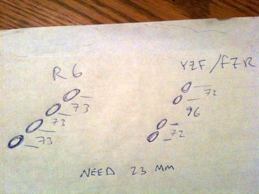
Did a quick and dirty to figure out approximately how much wider I have to make the R6 rack. I got 23mm will double check when I get some batteries for my digital calipers. Space is very tight in the FZR frame and I think with the 23mm extension it's going to be cutting it VERY VERY close. We'll see how it goes.
photo-264.jpg


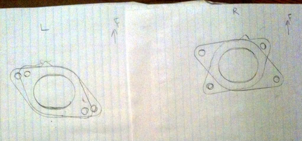
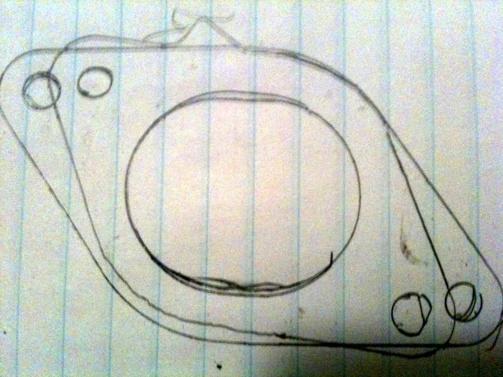
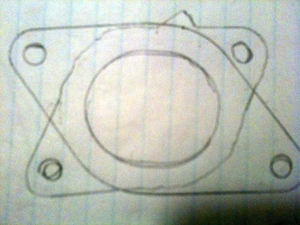
I overlayed the R6 throttle boots over the YZF/FZR boots that I have and the ports match almost identically. So I am thinking if there is room I can make an adapter plate for the left and right sides and then use the r6 throttlebody holders as they are instead of making such a custom piece that will no doubt need to be done and redone by a machine shop until it's right. This would be a more OEM route so hopefully it works.
photo-767.jpg

photo-1169.jpg

photo-2412.jpg
 
It will take a while to get them, but digital calipers go through batteries quickly.
http://www.dealextreme.com/p/cell-battery-ag13-lr44-50-pack-60

Thanks. I'll order some up.

Anyone know where I can get some clear plexiglass about 1/4" and 1/2" thich? I want to machine my adapter plates out of plexiglass first test fit as proof of concept especially since I can print out my AutoCAD drawings on the glass and use it as a template for drilling on the plexi-glass and then I'll make it out of aluminum once I have my final measurements and everything.
 
If I'm understanding this correctly, you need some plates with one set of counterbored holes that can be screwed down to the FZR cylinder head, but which have tapped holes in the correct orientation for the throttle body holders? In the one drawing, make sure the tapped holes aren't going to interfere with the counterbores - looks very close.

It won't be any easier to make these out of Plexiglas than to just go straight to aluminum. Just make sure your drawing is accurate.

Are the R6 throttle body holders sensitive to orientation? Some of them have a notch to clear the spray pattern from the injector, but if they don't, it might be possible to re-orient them to a different angle if the hole pattern is trouble.


Yes you are understanding the idea correctly. I just wanted plexiglass because I can drill it on a drill press nice and easy because I figure I may have to go through a few iterations and possible have to grind some other areas away and stuff and basically plastic will be a lot easier to deal with at first than aluminum. Once I convince my self this type of plate works I will have a final one made up out of aluminum.

And yes unfortunately the R6 ones have a specific orientation due to two things.
1) the ovalish shape of the port
2) The injector recess.

I thought about grinding out another injector recess which probably wouldn't be too hard and would probably have no ill effect that I can think of. But that still leaves the fact that the ports won't really line up all that well. However if I could somehow get around the ports not lining up it would be a TON easier to deal with.
 
Aluminum is easier to machine than plexiglas. Plastic tends to melt and gum up your tools. You might as well just go straight to aluminum. I would.

In the version that has the holes close together, would the tapped hole overlap the counterbore on the other hole?
 
Aluminum is easier to machine than plexiglas. Plastic tends to melt and gum up your tools. You might as well just go straight to aluminum. I would.

In the version that has the holes close together, would the tapped hole overlap the counterbore on the other hole?

No the holes won't overlap. But I was taking a closer look at the Head of the engine and it looks like my R6 boot might hit the head and not fit.

EDIT:
Definately hits the head.

So here is a thought since I need to put at least a half inch spacer in there for the TB rack to clear the head too, could I just orient the R6 manifold however I want and then reshape the R6 intake manifold with JBweld or similar epoxy?
 
Last edited:
JB Weld hardens when it cures, and if you try to attach it to rubber/plastic that is softer, it will crack and flake off and go into the engine. Badness occurs. Don't do that.
 
JB Weld hardens when it cures, and if you try to attach it to rubber/plastic that is softer, it will crack and flake off and go into the engine. Badness occurs. Don't do that.

I was going to grind the rubber layer away. It seems as though most of the boot is actually metal and rubber only painted on near the base. But yes I figured the JB wouldn't really adhere the best. I can't really think of too many other ideas besides going back to the original of a custom aluminum port and use another boot to clamp it to the throttlebodies but I am not really satisfied with that and it would cost me a minimum of $330 for all 4 and it's a solution I won't be totally happy with. I have to think some more on this. In the mean while if anyone has some good ideas would love to hear them.

One thing I was thinking about was grinding away some of the rubber on the base and then welding plates around the bottom. Effectively cutting off the existing flange from the intake manifold and welding on the other flange...
 
aluminum with some good quality bits (cobalt or regular jobbers will do too ) and a lot of cutting fluid to clear up the shavings......it works well.

keeping the bit clean and cool is the key
 
subscribed
 
Anybody who has an LM-1/LM-2 or LC-1 and is willing to let me test a display, let me know. I have all the hardware together, I just need to complete the software for a display and need one to test on. My LC-1 is sitting on my desk and I don't plan on installing it until the summer and I'm debating on waiting until I can get a decent new full exhaust.
 
OK ladies. I just disassembled the throttleboddies. No way in hell am I going to get another 23mm and have it fit between the frame rails. So I need a new plan. I am thinking new intake manifolds with a little angle to the flanges so they meet the r6 TBs as they are. Does anyone think this will cause mixture problems or anything like that? Asides from costing more to machine I think this a good idea because then the R6 TBs will be just a bolt on affair, so the money I save on a custom fuel rail etc can go towards a custom intake manifold set up.

Thinking something a long these lines. What kind of rubber boot can I use that will give me some flexibility to have an aluminum flange and a boot flexible enough to curve a little, but stiff enough to hold up the TBs? Or I was thinking something like this:
cfintakemanifold2.jpg


I know I know DIY carbon is too much etc. But it may very well be a decent solution if I can do it at home.
 
Last edited:
Trying something else right now. But need some peoples ideas and stuff. Well I am ordering the microsquirt today. And also the O2 sensor. Ebay says $155 for the sensor, and weld on bung and CD etc etc. If anyone has one on this side of the border close in price let me know.

I found more space between my frame rails by taking off the venting tube on the throttlebody. It now fits pretty well just need to move the vent holes to be between the two middle TBs.

But I still need to somehow move the TPS in 3 mm. and then we will be all good.

Now for my question. I want to glue R1 boots onto my YZF600 boots. Would contact cement be the correct glue to use? I need something that will seal so well or fuse the two surfaces and still be pliable because its on rubber and I don't want the seal to crack.
 
Last edited:

Back
Top Bottom