Assuming my switches can handle a straight through Cat 6 cable.
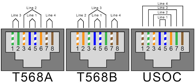
Why do I need the orange or the green wires separated (see pinout)?
Is there interference if they're wrapped together?
It's kind of a pain to get them threaded into the ends with the two wires split like that.
Is it necessary?
There are a couple of issues embedded in your questions.
Q: Why can't you just run the colours straight through, matching pin-out from one jack to the same pin-out on the other side, and not separate out pins 3 and 6?
A: Because of crosstalk. Pinouts 3 and 6 are the RD+ (Receive Data Positive) and RD-. These need to be intertwined in a single twisted pair so they can eliminate interference and degradation from the other wires in the bundle.
Q: Ok fine, then why are pins 3 and 6 separated at the jack? Why does the Ethernet (or more specifically, the MDI) specification make it so difficult to crimp? Wouldn't it be easier to have the orange/orange-white twisted pair terminate at pinouts 3 and 4?
A: Because the original specification for T568A had to be backwards compatible with the old USOC standard that 4-pin telephone jacks (RJ-11) used. If you look at the original USOC spec, you'll see the logic:
The inside 4 pins of T568A had to preserve compatibility with USOC. You can see if you plugged a RJ-11 telephone plug into an ethernet port, the first phone line is carried by pins 4 & 5, and the second phone line is carried by pins 3 & 6. I assume that after that, T568 didn't care any more, so they just paired pinouts 1 & 2 and 7 & 8 together to make it easier for crimpers?
And that, kids... is how I met your mother...


