Headlights Issue. Checking Relay? | GTAMotorcycle.com

Headlights Issue. Checking Relay?

architect

Well-known member
Site Supporter
I have a 2009 ZX6R track bike that I'm converted back for street use. Still has OEM wiring harness that's untouched from what I can tell.

Everything works fine except no power to both sockets of high and low beam. I tested with a multimeter with the bike/engine running. I took the cluster off, so can't tell if the high beam indicator comes on. All other lights such as front and rear signals, daytime running, and brake lights work just fine. Fuses are fine. The aftermarket LED headlight also works without issue if I power them from signal or daytime running sockets. From what I gather online and in the manual, it could be the rectifier or relay, but this is where my knowledge and abilities end. I'm confused on how to check the relay as per the manual (but I'm also doubting that's the issue).


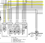
Font Parallel Number Pattern


Font Parallel Rectangle Pattern Diagram


What do I connect exactly together with the multimeter and the battery to what configuration? I'm new to electrical stuff looking for some more specific diagnostic instructions. Thanks.
 
Forget the test procedure. You don't have the "Kawasaki hand tester".

Ground pin 11 throughout this procedure.

Momentarily connect +12V to pin 2. You should hear the relay click.
Momentarily connect +12V to pin 1. You should hear the relay click.

Check resistance between pins 1 and 3 without power applied. It should be open circuit (infinite resistance).

Apply +12V to pin 1 (relay clicks) and then, while this power remains on, measure voltage between pin 3 and ground. It should be battery positive voltage.

The interconnect at pin 11 is to the starter contactor so that when power is applied to the starter contactor (pin 11), the battery voltage at pin 11 causes the headlight relay to drop out and this turns the headlight off while the starter motor is being used. (When the starter contactor is not applied, the current from the headlight relay intentionally leaks to ground through it but is insufficient to pull the contactor in.) What this also means is that the starter contactor circuit needs to be connected. Presumably since you say that the bike runs, the starting motor circuit works, which means the starter contactor is connected, which means this isn't the issue.

The bike's circuit diagram should show you where power to pins 1 and 3 is coming from. Check whether it does. It may be tricky with the relay box unplugged from the bike.
Thanks for this write-up, Brian. Super helpful. It'll take me some time for me to digest and apply as I'm very new to electrical.

Few basic questions:
Is this test with the relay off the bike, or on bike and just battery disconnected?
If on the bike, do I ground pin 11 directly to bike frame?
When you say connect/apply +12V to pin X, I just take the positive terminal from the battery to said pins?

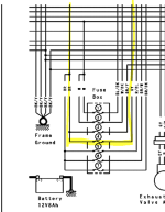
I looked at the wiring diagram and what seems odd is the GY wire from headlight relay is connected together with the BR wire on the fan relay after passing through their own fuse:

1726583969524.png
1726584105957.png
 
I'm not seeing where GY and BR are connected except via the fuse. BR is ignition-key-switched power before the fusebox and GY is logically the same but after the fuse. The excerpt doesn't show it but I'm thinking fuse 4 is the headlight fuse and GY is thus power to the headlights.

So with this excerpt we can see that:
Headlights are "kicked on" by the G wire (wherever that's coming from). Power from G goes through the diode through the coil of relay 2 (headlight) and then leaks to ground through the starter relay/contactor (insufficient current to make the relay pull in). It is possible that G is fed from something that only operates when the engine is running (so that key-on engine-off, the headlight doesn't initially turn on).

When you press the starter button, the voltage applied to pin 11 (Y/R which will lead to the starter contactor coil) leads to both sides of the coil of relay 2 having battery power on them, i.e. no current, headlight relay drops out and turns the headlights off while the starter contactor is applied.

After the starter contactor is released then the "kick-on" circuit via wire G happens as described above.

Once the headlight relay is pulled in, then it "latches on" (as long as the starter is not being used). Power flow from + to - is: wire GY (ignition-switched power via headlight fuse), through the closed relay contact, then out of the relay box via BL wire (leads to the high/low-beam switch) but also through that cross-connect over to pin 11 and the Y/R wire over to the starter relay which leaks it to ground.

That's what's supposed to happen. Investigate where the power for wire G is coming from. It isn't shown on the excerpt provided.
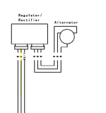
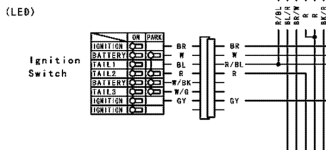
1726607937114.png1726608066522.png

G comes from the rectifier. W to the left of G goes to 'battery' on the ignition switch. Could the rectifier also be the culprit then?
 
OK, so G is an output from the regulator/rectifier to indicate that the alternator is operating, i.e. if the engine is spinning and the alternator is alternating, then G turns on in order to turn the headlights on.

Test: Have everything in the bike plugged in as it's supposed to be except the plug on the regulator/rectifier that contains the W (white - unswitched battery positive) and G and BK/Y (ground) wires. Key on engine off. Use a jumper wire to connect G to W on the harness side of that plug (which jumpers unswitched +12 to G). The headlight should come on. If it does, your relay box is OK and the problem is that the regulator isn't producing the G signal. If it does not, inspect wiring harness for continuity of the G circuit between the regulator/rectifier harness plug and the relay-box harness plug.
Thanks, Brian. Followed your method and found that the regulator is fine but the harness plug at regulator was the issue. Seems like one of the wire at the plug was crushed and really hard to tell unless looking for this closely.
 

Back
Top Bottom