


You are using an out of date browser. It may not display this or other websites correctly.
You should upgrade or use an alternative browser.
You should upgrade or use an alternative browser.
2010 ZX10R Superbike Build
- Thread starter caboose56
- Start date
Bikes lookin good! I'm intrigued as to what this swingarm is going to look like.
I have the same triples on my gsxr1000 but haven't had a chance to play with them. I got a chart with the settings from the builder/first owner and it looks like once you get them set you don't change them, they left them the same for all the tracks run in the nationals that year.
I have the same triples on my gsxr1000 but haven't had a chance to play with them. I got a chart with the settings from the builder/first owner and it looks like once you get them set you don't change them, they left them the same for all the tracks run in the nationals that year.
Update!
I had initially requested the 2 inserts for the Attacks but they sent me 3s. After talking to the guys at Attack I'm going to start with the 2s. Once I get the inserts back I'll take a few pics that show how the Attack triples do what they do.
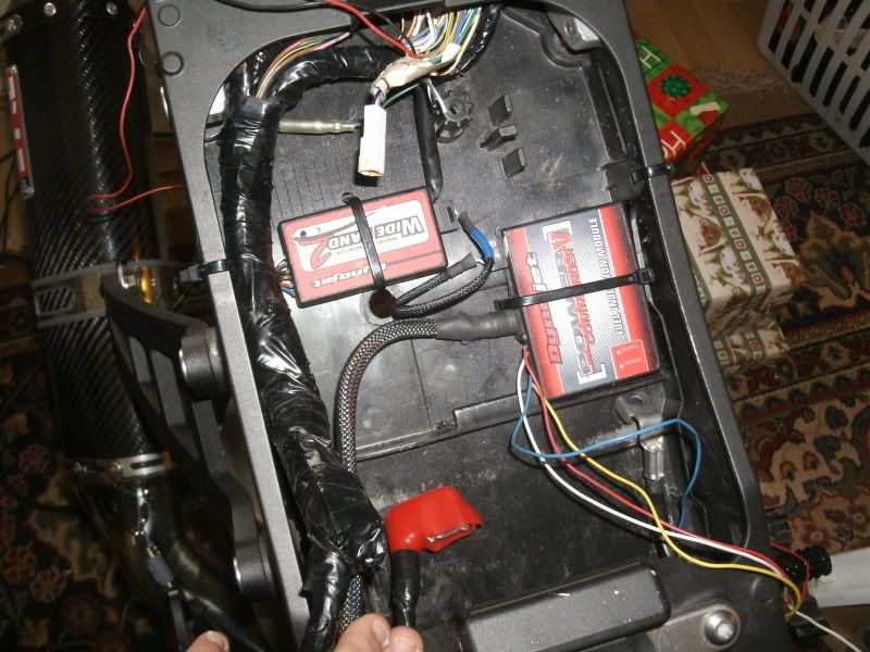
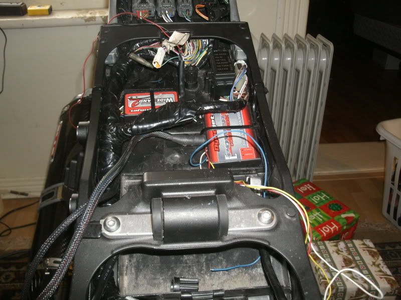
I got the PowerCommander V and Autotune module mounted up today. I'm not going to hook anything up at the moment. The first thing to do is get the bike start and make sure everything is running properly in stock form. After that's sorted and verified I'll be hooking up the electronics. Getting rid of the exhaust servo motor opened up a lot of room to install stuff.
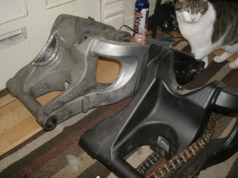
New swingarm is installed on the bike. I'll take a pic of everything installed once I get my Ohlins shock back from Brad Clarke (Compulsion Racing). Basically, there will be interference between the shock and swingarm since my shock is actually off a 1st Gen 10R. Dean Plater had the 3rd Gen swinger on his 2nd Gen 10R and had to notch it but he didn't like the handling changes with the longer swingarm so he abandoned that plan... knowing the right people is handy.
Anyhow. Here's some pics. I should have the Attack triples, shock and fork installed before New Years.
I had initially requested the 2 inserts for the Attacks but they sent me 3s. After talking to the guys at Attack I'm going to start with the 2s. Once I get the inserts back I'll take a few pics that show how the Attack triples do what they do.
I got the PowerCommander V and Autotune module mounted up today. I'm not going to hook anything up at the moment. The first thing to do is get the bike start and make sure everything is running properly in stock form. After that's sorted and verified I'll be hooking up the electronics. Getting rid of the exhaust servo motor opened up a lot of room to install stuff.
New swingarm is installed on the bike. I'll take a pic of everything installed once I get my Ohlins shock back from Brad Clarke (Compulsion Racing). Basically, there will be interference between the shock and swingarm since my shock is actually off a 1st Gen 10R. Dean Plater had the 3rd Gen swinger on his 2nd Gen 10R and had to notch it but he didn't like the handling changes with the longer swingarm so he abandoned that plan... knowing the right people is handy.
Anyhow. Here's some pics. I should have the Attack triples, shock and fork installed before New Years.
Not much has changed. Swingarm and Ohlins shock have been installed. I've encountered some headaches with the Attack clamps and after some discussions with them on the phone we've figured out that there was a mix up and I have a kit for a 2011 10R, not a 2010 so they are sending me the right parts. The stand im using to support the bike right now requires the rad to be removed. So once the Attack clamps are installed I can install the rad, button up the cooling system then make sure she's running properly in stock form. After that I can wire in the PowerCommander and 02 sensor module.
Slowly.. we're gettin there.
Slowly.. we're gettin there.
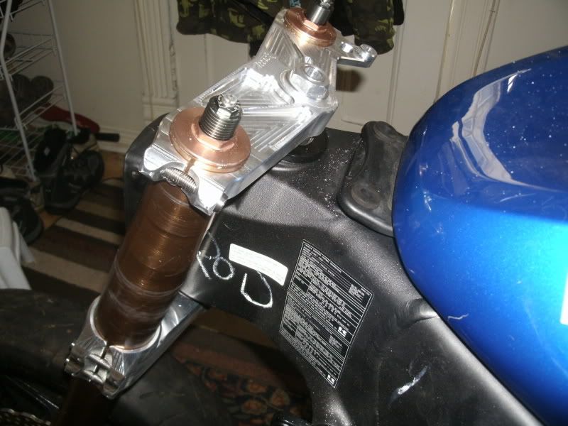
Ok so I haven't updated in a while. I had a bit of a headache with Attack and the triple clamps. It ended up being a really silly problem, they sent me clamps for a 2011 10R, not a 2010. It took a bit of discussion to figure out why my clamps and forks weren't fitting properly. Anyhow, all is good now and the build continues!
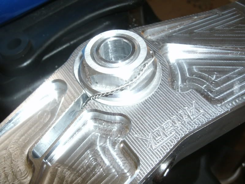
The Attack clamps installed with the stem nut safety wired.
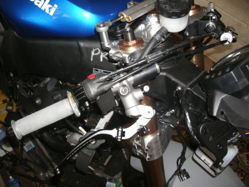
Hand controls being installed. The 1/5th turn throttle I used on my 04 works perfectly on the new bike. No modifications needed. Woodcraft clipons and Accossato master cylinder.
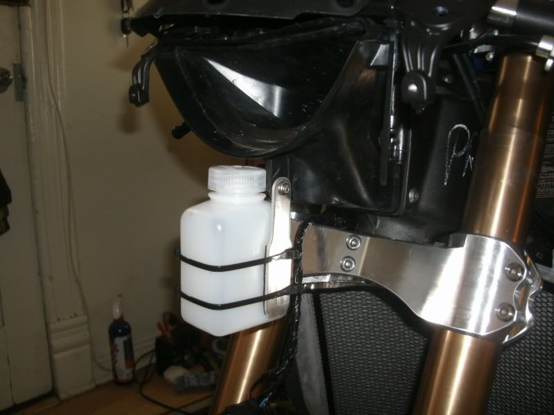
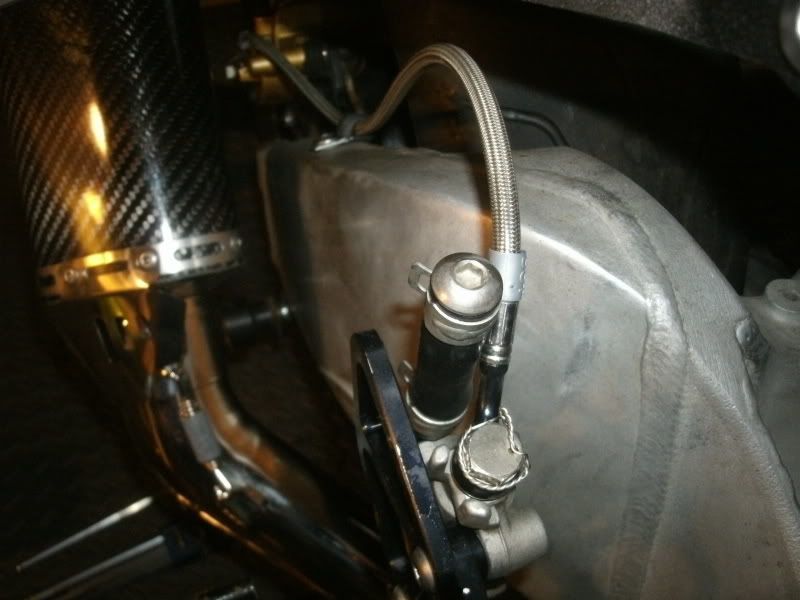
Remote coolant reservoir. Often the OEM res is in a vulnerable spot. This one is fairly well protected. I got the bottle at Mountain Equipment Co-op in their camping gear section.
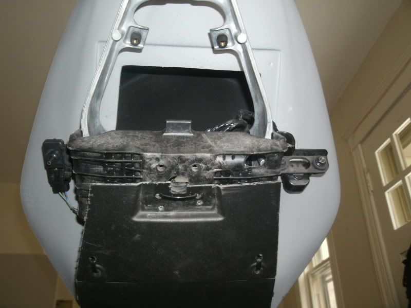
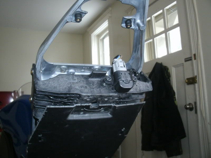
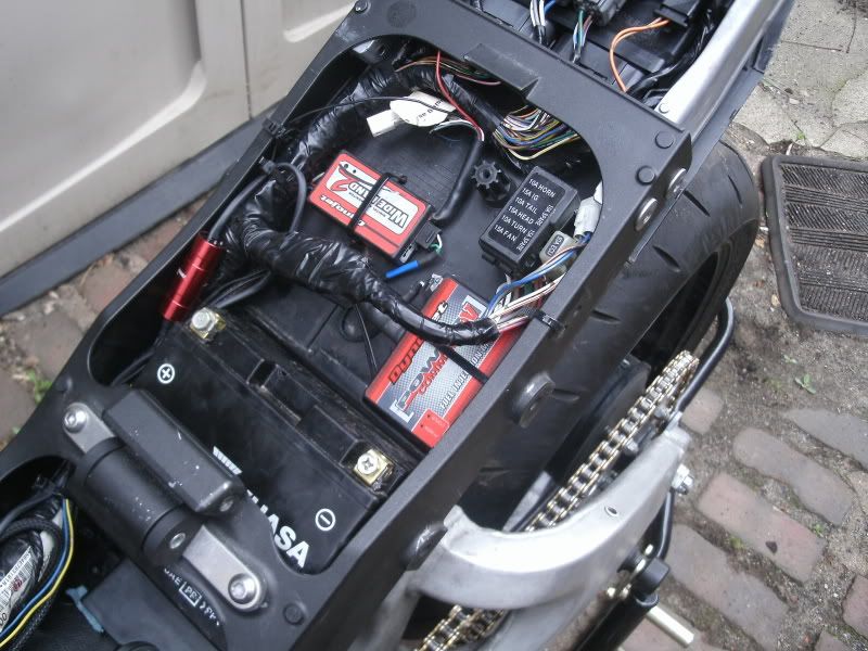
There's some electronics on the subframe that make installing the tail a pain in the ass so they've been relocated.
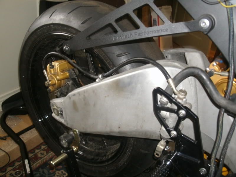
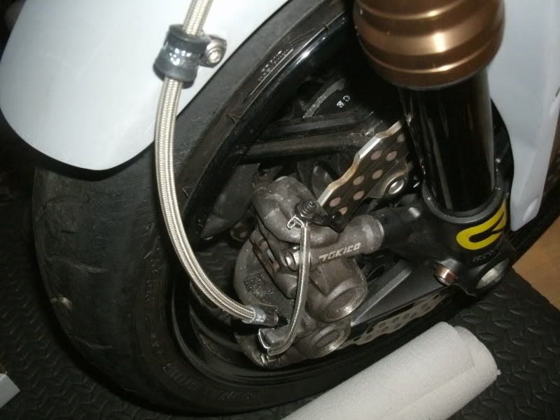
The rear brakes from my 04 bolt up fine. Saves me some drilling and safety wiring.
The Attack clamps installed with the stem nut safety wired.
Hand controls being installed. The 1/5th turn throttle I used on my 04 works perfectly on the new bike. No modifications needed. Woodcraft clipons and Accossato master cylinder.
Remote coolant reservoir. Often the OEM res is in a vulnerable spot. This one is fairly well protected. I got the bottle at Mountain Equipment Co-op in their camping gear section.
There's some electronics on the subframe that make installing the tail a pain in the ass so they've been relocated.
The rear brakes from my 04 bolt up fine. Saves me some drilling and safety wiring.
What's the benefit of the modified swing arm? Just to clear the shock resevoir?
What's the benefit of the modified swing arm? Just to clear the shock resevoir?
Yes exactly. Only a hand full of people around here have the vacuum chamber required to rebuild a TTX shock. The PRXLS is a lot easier to work on.
more importantly, does your cat have a blue eye and a green one? or is that the camera playing tricks.. its cooler if thats real!!
more importantly, does your cat have a blue eye and a green one? or is that the camera playing tricks.. its cooler if thats real!!
It's just the camera playing tricks. Sorry to disappoint!
more importantly, does your cat have a blue eye and a green one? or is that the camera playing tricks.. its cooler if thats real!!
Hahah, u stole the question outta my mouth.
I was wandering if he can help with the install. As they say, many hands make light work

Hahah, u stole the question outta my mouth.
I was wandering if he can help with the install. As they say, many hands make light work
He's not very helpful to be honest. But whenever something changes he's very curious, I don't think he likes change. As the bike comes together he's often inspecting it to make sure everything is ok.
He's not very helpful to be honest. But whenever something changes he's very curious, I don't think he likes change. As the bike comes together he's often inspecting it to make sure everything is ok.
You've got a quality inspector on your hands
I got my exhaust back from having the O2 sensor bung welded in.
Finished some more safety wiring, installed the chain, front brake lines and exhaust, filled the rad then took er outside. The bike that became my pile of parts was never winterized properly so the fuel in the injectors would have been somewhat old. Starting with a fresh battery charge it took 3-4 start attempts before she started to sputter, another 3-4 attempts before she caught for a few seconds then stalled, and one more try before she fired up..... but on 3 cylinders.. then about 5 seconds later there was a little backfire and the 4th cylinder picked up. I let er warm up for a few minutes before even touching the throttle but everything seems to be working fine. The Yoshimura sounds very nice... and angry.
It was near freezing outside so I was able to let her run for about 15 minutes up to operating temperature. No leaks, no noises (other than typical Kawi valve chatter), nothing caught on fire. So far so good. I'll take some pics of the safety wire and such soon and post them up. Princess Auto has the vacuum pump kit on sale starting tomorrow so I will be picking that up to help bleed the front brakes. After that I will be hooking up and setting up the PowerCommander and AutoTune as well as the Annitori quickshifter. Not much left after that!
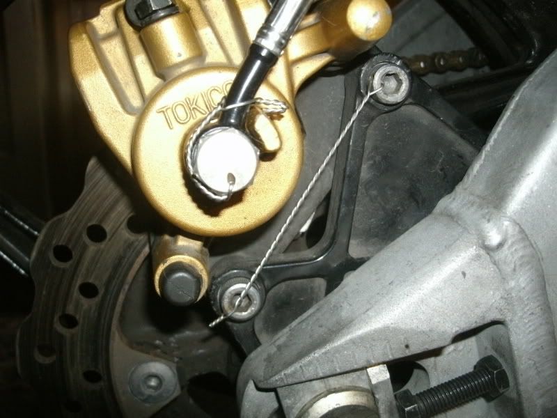
Ok I have some more pictures! Working on electronics stuff and safety wire. The braking system in place now is actually from my 04 10R. I had the Galfer rear line on there but it was a bit long so it's been replaced with a Spiegler rear line. I've also rigged up the mini rear brake fluid reservoir, yes it's small but it's all that I need. Spiegler front lines are installed as well. Not too many riders use the line looms that I do but I hate having the lines rubbing against the fender all the time. The way they're set up now the brake lines don't contact anything on the front end. The looms you can get in bulk at Princess Auto for next to nothing. Make sure you get rubber lined looms tho.. ")
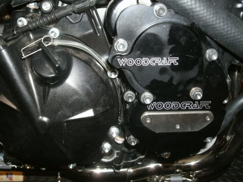
Woodcraft case cover installed. Also note the safety wire tether for the oil filler cap. These clips are really handy for items that you'll be removing often. Caliper bolts, oil filler cap, drain plug, etc. I drilled out one of the clutch cover bolts for the tether. There are other items nearby I could wrap the safety wire around but the clutch cover bolt was the cleanest solution.
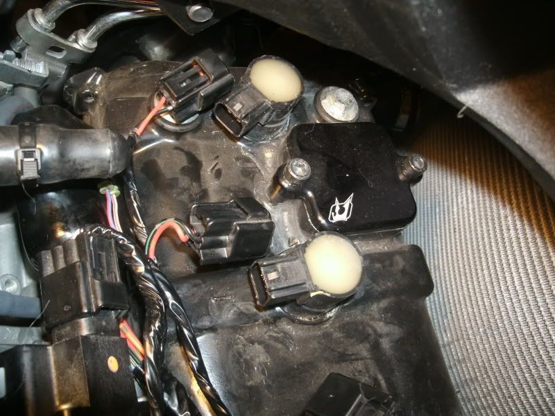
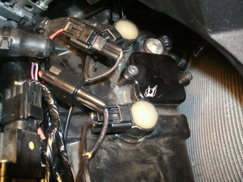
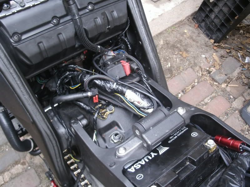
After that was installing the Annitori RL quickshifter. The Annitori works as a spark kill, unlike the Dynojet system which is a fuel kill system. The first pic shows the main wiring harness attaching to the coil packs in the cylinder head. The second pic shows the quickshifter wiring harness.
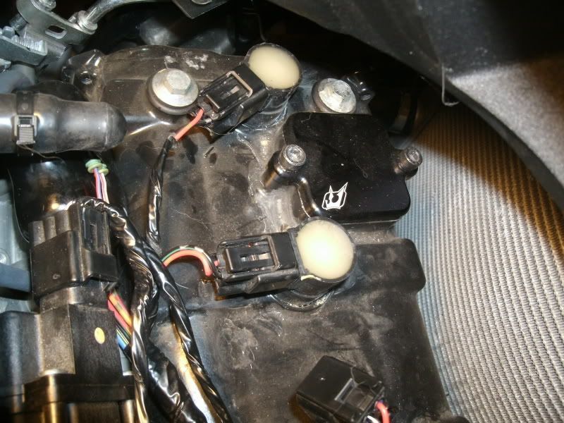
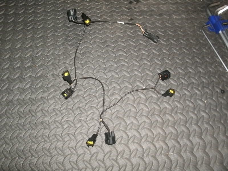
Unplug the main harness from the coil packs, plug the Annitori harness into the coil packs then plug the main harness into the Annitori harness. Hopefully that makes sense. Basically the Annitori goes between the main harness and the coil packs and is a ground interrupt.
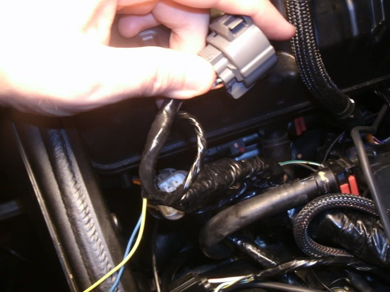
Next, more wiring. The PowerCommanderV requires a signal from the speed sensor and the water temp sensor. Luckily both wires are in the same connector just behind the airbox. A quick strip and solder and they're all set to plug into the PCV.
Next was the keyless ignition mod. Step one is to jumper the wires to the kill switch together, essentially making the kill switch always in the closed position. This leaves the kill switch available to act as the ignition on/off switch.
Then combine the ignition switch harness and the RH handlebar harness. The power supply that went to the ignition switch will now go to the kill switch. There are two power signals that ordinarily go from the ignition switch to the ECU. One is a direct 12V power supply and one runs through a resistor in the original ignition switch. That resistance must be replicated for the keyless system to work, hence the resistor. I also need to keep power going to tail light harness because that's supplying power to the Autotune module.
This is the same thing I did to my 2004 10R and it worked flawlessly for me and I never have to worry about forgetting my keys or how to mount the ignition switch to the Attack clamps as they offer no provision for mounting them. Also, saves weight. Good stuff!
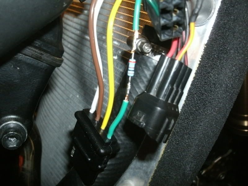
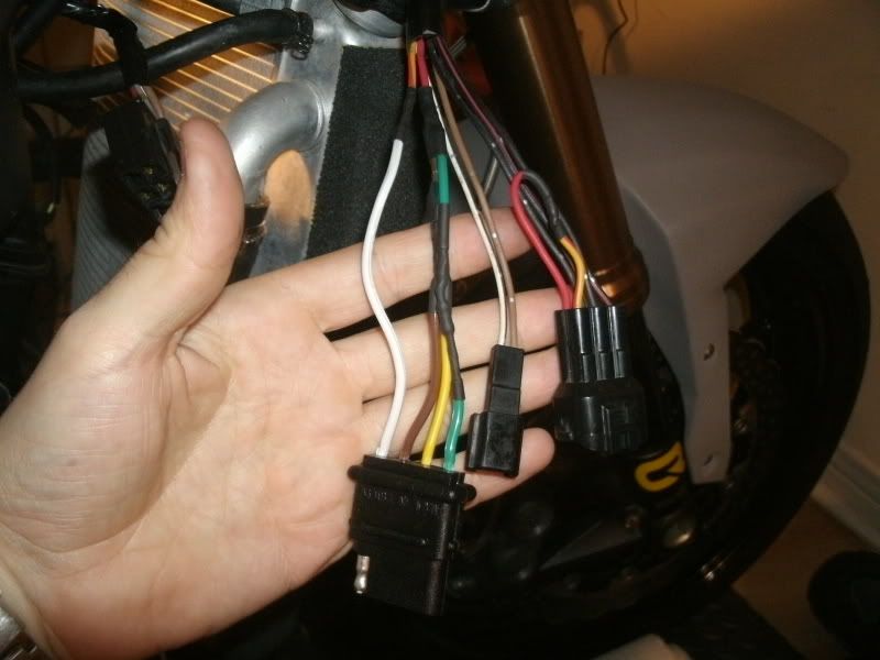
After all the soldering is done, just wrap up the harness with electrical tape and it's good to go.
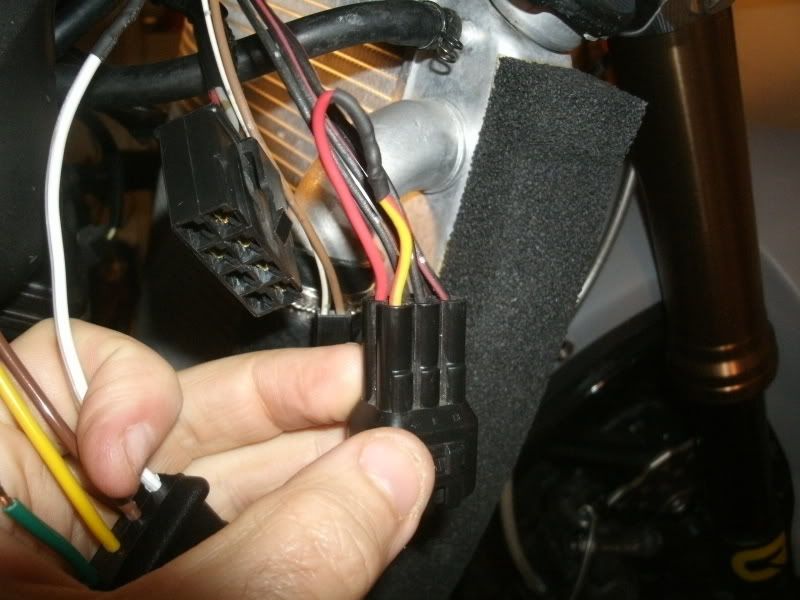
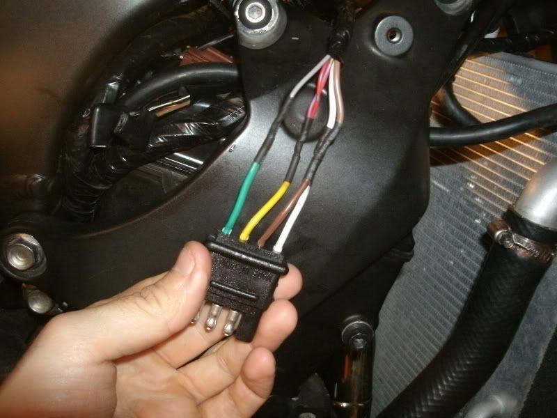
Next is the corresponding section of the main harness. I used the flat-4 pin connector (yup, it's just a 4 pin trailer wiring harness connector from Princess Auto... $4.. no need to over complicate it) on the main side so I didn't have to hack apart the OEM ignition switch harness. With the ignition switch intact I can sell it.
Woodcraft case cover installed. Also note the safety wire tether for the oil filler cap. These clips are really handy for items that you'll be removing often. Caliper bolts, oil filler cap, drain plug, etc. I drilled out one of the clutch cover bolts for the tether. There are other items nearby I could wrap the safety wire around but the clutch cover bolt was the cleanest solution.
After that was installing the Annitori RL quickshifter. The Annitori works as a spark kill, unlike the Dynojet system which is a fuel kill system. The first pic shows the main wiring harness attaching to the coil packs in the cylinder head. The second pic shows the quickshifter wiring harness.
Unplug the main harness from the coil packs, plug the Annitori harness into the coil packs then plug the main harness into the Annitori harness. Hopefully that makes sense. Basically the Annitori goes between the main harness and the coil packs and is a ground interrupt.
Next, more wiring. The PowerCommanderV requires a signal from the speed sensor and the water temp sensor. Luckily both wires are in the same connector just behind the airbox. A quick strip and solder and they're all set to plug into the PCV.
Next was the keyless ignition mod. Step one is to jumper the wires to the kill switch together, essentially making the kill switch always in the closed position. This leaves the kill switch available to act as the ignition on/off switch.
Then combine the ignition switch harness and the RH handlebar harness. The power supply that went to the ignition switch will now go to the kill switch. There are two power signals that ordinarily go from the ignition switch to the ECU. One is a direct 12V power supply and one runs through a resistor in the original ignition switch. That resistance must be replicated for the keyless system to work, hence the resistor. I also need to keep power going to tail light harness because that's supplying power to the Autotune module.
This is the same thing I did to my 2004 10R and it worked flawlessly for me and I never have to worry about forgetting my keys or how to mount the ignition switch to the Attack clamps as they offer no provision for mounting them. Also, saves weight. Good stuff!
After all the soldering is done, just wrap up the harness with electrical tape and it's good to go.
Next is the corresponding section of the main harness. I used the flat-4 pin connector (yup, it's just a 4 pin trailer wiring harness connector from Princess Auto... $4.. no need to over complicate it) on the main side so I didn't have to hack apart the OEM ignition switch harness. With the ignition switch intact I can sell it.
Last edited:
Big day today!
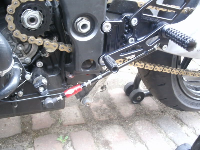
Finished installing the Annitori quick shifter. I had the shift arm mounted on the wrong side initially as shown in the pic. I have since flipped it so its GP shift.
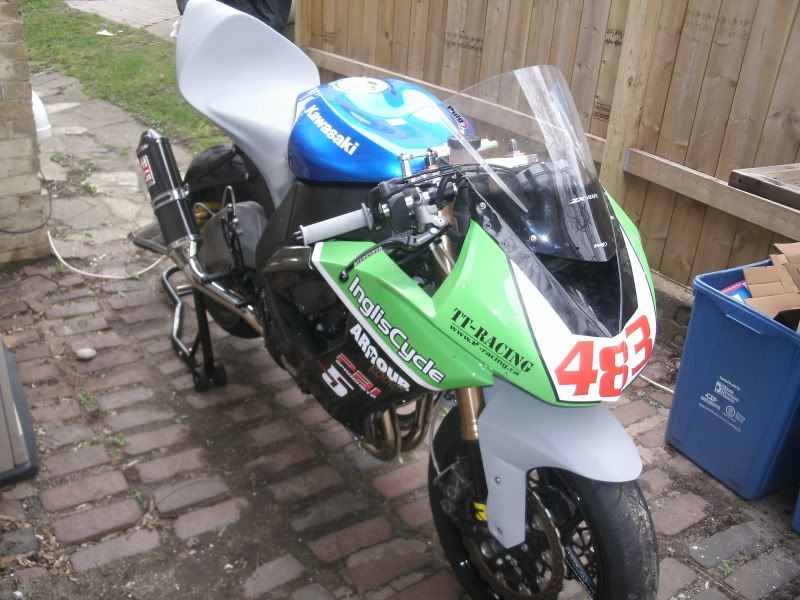
Wiring under the seat and tank is as tidy as I think I can make it. Pretty good and reasonably well organized. Put the tank back on and installed the tail. The Armour Bodies tail has a built in seat support and fits very snug. Its a bit delicate to get it installed over the subframe but once its on it fits really really well. The upper is the same Gen 3 upper I ran on my 04. Good thing I saved it!
Put the bodywork on and fired her up. She's still angry and needs a good run I think. Get some good fuel run through her. I forgot to jumper the side stand switch wiring so my first attempt at a test ride didn't go very far. 15 minutes later I had the connector removed and the two wires jumpered together.
Fired her up, put on my helmet and took her for a ride around the neighbourhood. Everything seems to be working! Brake pedal and shift lever need adjusting as expected but everything else is green lights across the board so far.
Finished installing the Annitori quick shifter. I had the shift arm mounted on the wrong side initially as shown in the pic. I have since flipped it so its GP shift.
Wiring under the seat and tank is as tidy as I think I can make it. Pretty good and reasonably well organized. Put the tank back on and installed the tail. The Armour Bodies tail has a built in seat support and fits very snug. Its a bit delicate to get it installed over the subframe but once its on it fits really really well. The upper is the same Gen 3 upper I ran on my 04. Good thing I saved it!
Put the bodywork on and fired her up. She's still angry and needs a good run I think. Get some good fuel run through her. I forgot to jumper the side stand switch wiring so my first attempt at a test ride didn't go very far. 15 minutes later I had the connector removed and the two wires jumpered together.
Fired her up, put on my helmet and took her for a ride around the neighbourhood. Everything seems to be working! Brake pedal and shift lever need adjusting as expected but everything else is green lights across the board so far.
Yummm AutoTune ")
-Jamie M.
-Jamie M.
Oh good thing!Big day today!
Finished installing the Annitori quick shifter. I had the shift arm mounted on the wrong side initially as shown in the pic. I have since flipped it so its GP shift.
Wiring under the seat and tank is as tidy as I think I can make it. Pretty good and reasonably well organized. Put the tank back on and installed the tail. The Armour Bodies tail has a built in seat support and fits very snug. Its a bit delicate to get it installed over the subframe but once its on it fits really really well. The upper is the same Gen 3 upper I ran on my 04. Good thing I saved it!
Put the bodywork on and fired her up. She's still angry and needs a good run I think. Get some good fuel run through her. I forgot to jumper the side stand switch wiring so my first attempt at a test ride didn't go very far. 15 minutes later I had the connector removed and the two wires jumpered together.
Fired her up, called insurance and put it on the bike, put on my helmet and took her for a ride around the neighbourhood. Everything seems to be working! Brake pedal and shift lever need adjusting as expected but everything else is green lights across the board so far.
Oh good thing!
Of course. All race bikes have insurance on them.