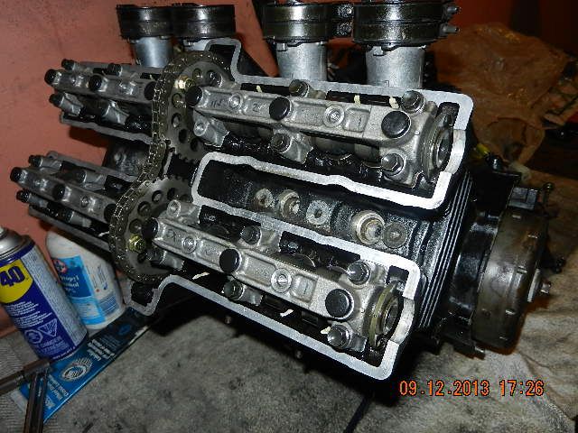
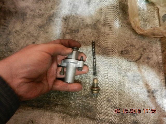
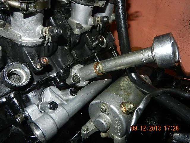
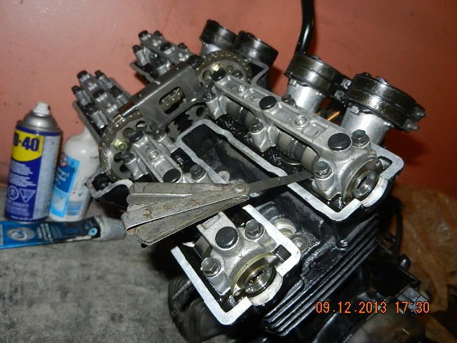
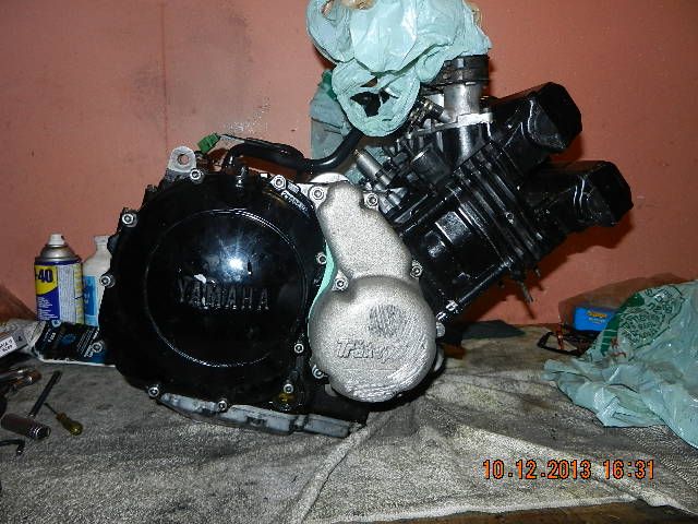
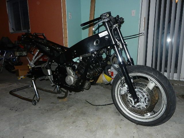
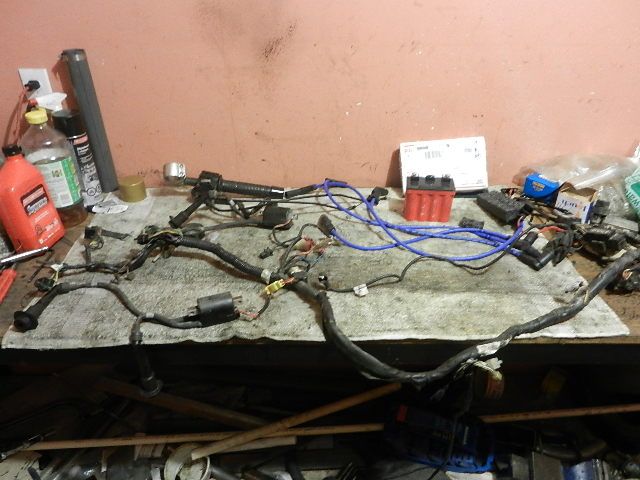
^ Ouch. Having to do things twice stinks. Been there ...
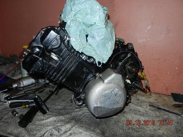
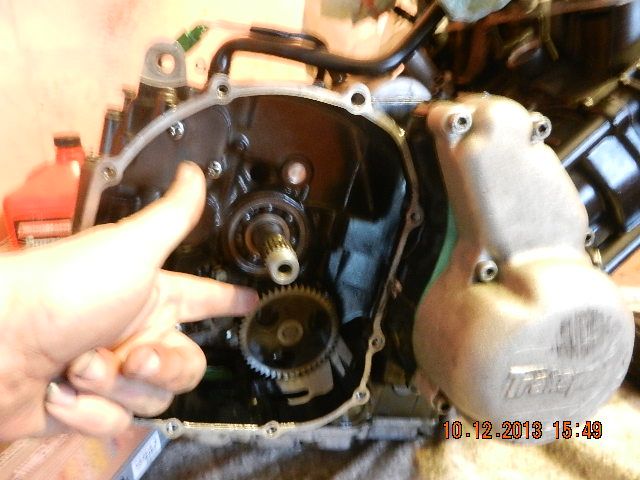
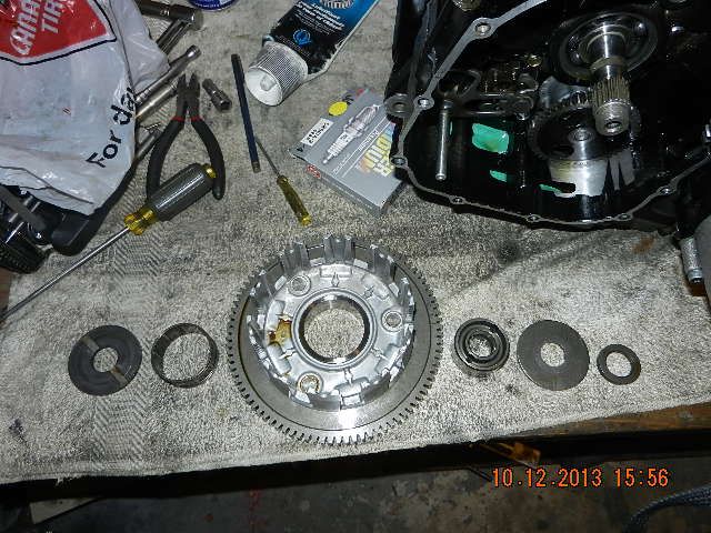
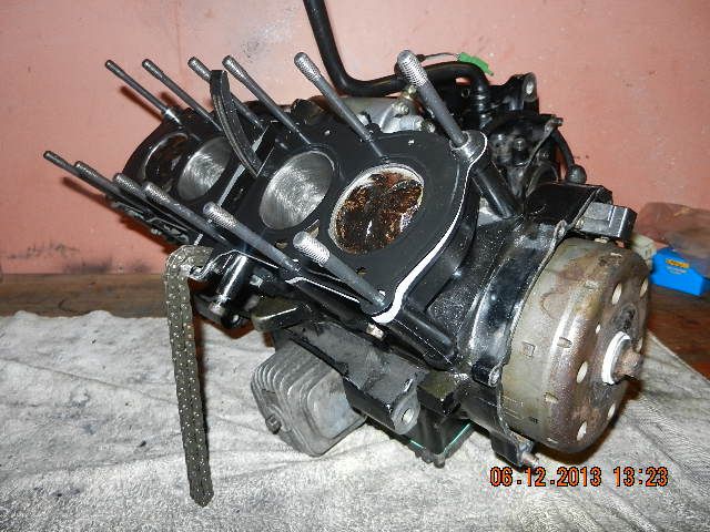
Update time. Here is the engine assembled up to the head gasket with the flywheel installed ... and there is an invisible trick here: the flywheel is assembled without the locating key such that the ignition timing is advanced about 3 degrees. Free timing advancer! The bolt on the end holds the flywheel (which has the tabs for the ignition pickup coil on the outside) on the tapered end of the crankshaft. The key doesn't transfer any of the load - it only holds orientation while the bolt gets tightened. That taper holds the flywheel VERY tightly (to the point of being very difficult to remove). VW diesels have their timing pulley secured to the camshaft in exactly the same way (taper, no key, the orientation is held with a locking tool while tightening the bolt) and that's an even more critical application. What made this possible (and easy) is that the cylinder head is off, so it's very easy to see and measure where exact top-dead-center is. Note the brand new crosshatch pattern in the cylinders.
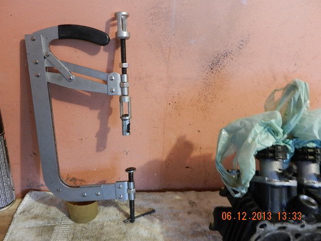
The next step involves this ... a valve spring compressor from Princess Auto, that has been modified to suit this engine. This tool being originally designed for cars, the fixtures that it comes with are too big for the valves in this engine. So, that extra little smaller-diameter piece with the window in it is something that I made up, and there is a rubber washer in the pocket at the bottom that allows the smaller-diameter valve to be clamped (and the rubber washer distributes the force evenly without any chance of causing scratches or other damage to the valve).
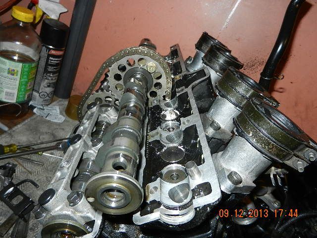
I didn't take pictures of the disassembly and modifications made to the intake ports, because the insides of intake ports don't photograph too well. But essentially, if you want to do some reading on what I did, here is something to dig through:
http://www.mototuneusa.com/power_news_--_think_fast.htm
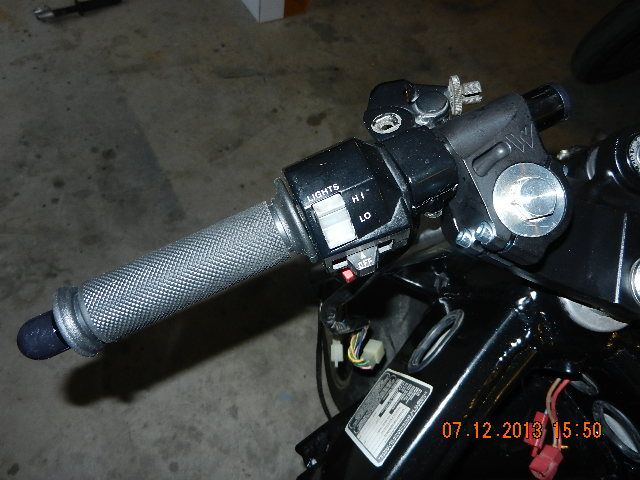
On a completely unrelated matter, I installed new Woodcraft handlebars while waiting for JB Weld to cure in the cylinder head.
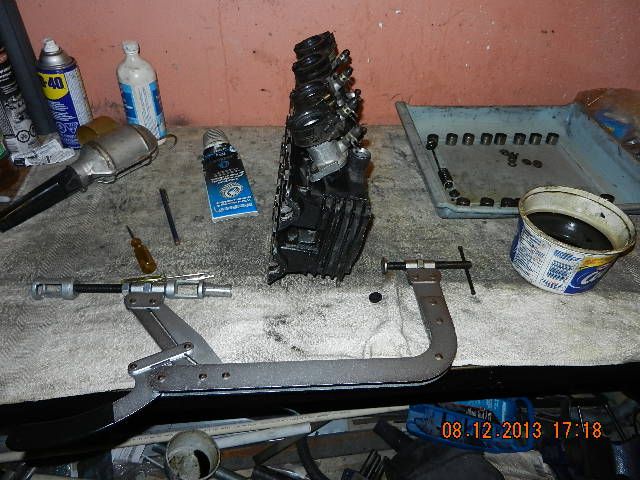
The tricky bit with cylinder head work isn't getting the valves apart ... it's putting them together. It is a finicky job. Here is what's needed: valve spring compressor (customized to suit this cylinder head), a container of oil, some wheel bearing grease, a portable lamp, tweezers, a magnet on a stick (for fishing steel bits out when - not if - you drop them), and various magnetic and nonmagnetic poking and prodding tools. The blue tray at right had all the components laid out in order so that every valve can go back into the same place that it came from. I didn't take pictures until doing the last one.
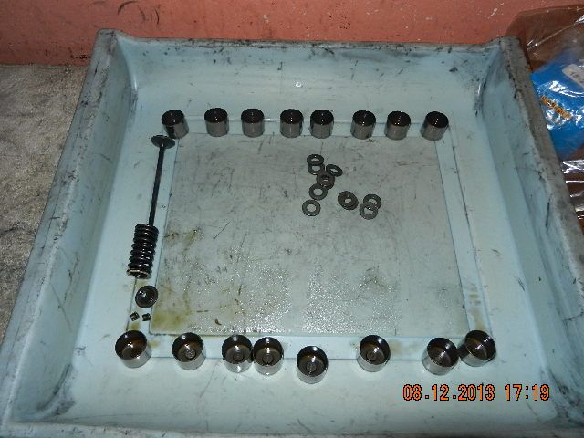
This is the valve mechanism. Not shown (and already in the cylinder head) is a steel spring seat and the valve stem seal. The spring pushes outward on the retainer, and that pulls the valve stem closed through the two little finicky keepers. The camshaft pushes the valve open through the bucket and the clearance-adjusting shim (still inside the bucket in the picture) and that acts on the valve stem directly to open the valve while the spring pushes it shut. The orientation of the spring is important ... it's quite possible to install the spring upside down. In this case, the end with the tight coils goes towards the head and the more open end goes towards the retainer. Ignore the random pile of washers ... those go under the cylinder head nuts later.
After dipping the end of the valve in oil, it gets inserted through the valve guide and stem seal (in the head already) like this ...
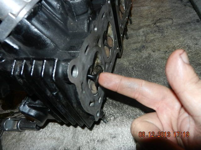
... then a little dab of grease goes on the end of the valve where the groove is, that the keepers will later be locking into.
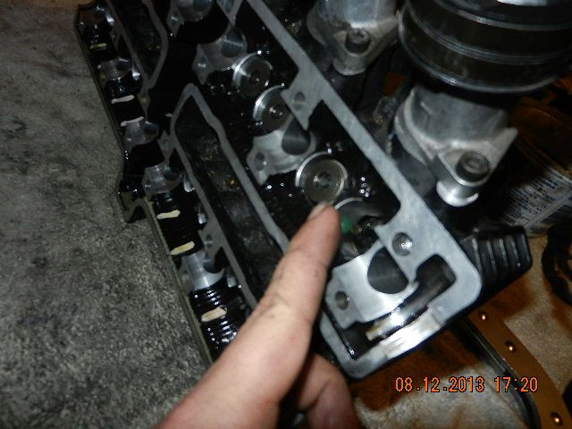
Then the valve spring goes in as shown - tight end towards the head - with the spring seat already in the head - and the retainer goes in on top of the valve; note the tapered section that will later lock in the keepers. On this engine, the retainers are steel. A lot of newer engines have aluminum or titanium retainers ... that's part of how 600cc bikes nowadays will rev higher than this 400cc bike ... but on the other hand, steel retainers will never break, and that can't be said of a good many newer engines ...
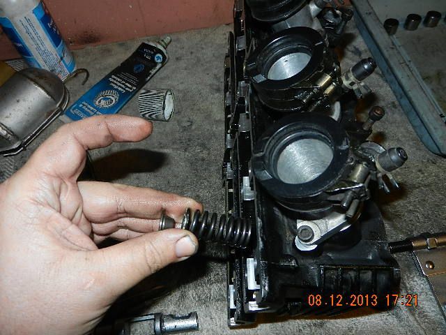
Then the valve spring compressor is used to push the retainer down against the spring, and the other end of it is against the valve with the rubber washer shown before to cushion it.
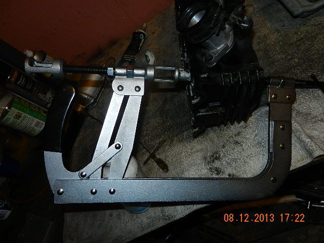
Here you can see the retainer pushed down just far enough to expose the end of the valve stem with the grooves for the keepers, with the window in the tool positioned to allow the keepers to be inserted.
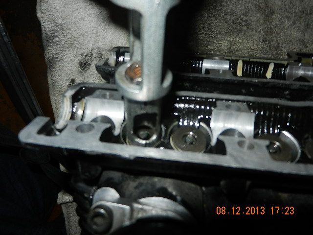
And then comes the son-of-a-gun job. Pick up a keeper with tweezers ...
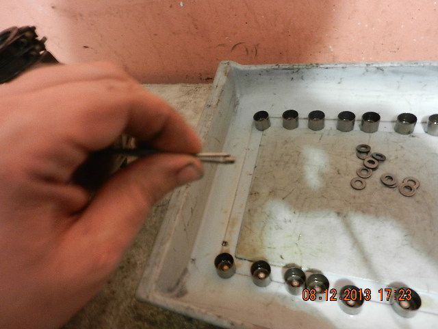
... and insert it on the end of the valve stem using the dab of grease to hold it in place, then insert the other one, so that it ends up like this.
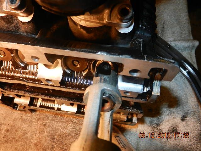
Or so the theory goes. Do not do this part of the job with small children within earshot. Allow 10 times longer to do it than you think you will need. In reality, there is no room to work, the keepers and your tools have been magnetized (a magnet is the only practical way to pick them up during disassembly - and when you drop them during reassembly), the magnetism is sometimes a blessing and sometimes a curse (which is why one of the non-magnetic poking and prodding tools is a toothpick), and the way the keeper is supposed to be oriented has the heavy end up, which means when you drop it, it always falls the wrong way so that you have to fish it out (magnet) and do it again. After at least 10 tries each, eventually they can be coaxed into sitting in the right spot, and upon removing the valve spring compressor, you have this:
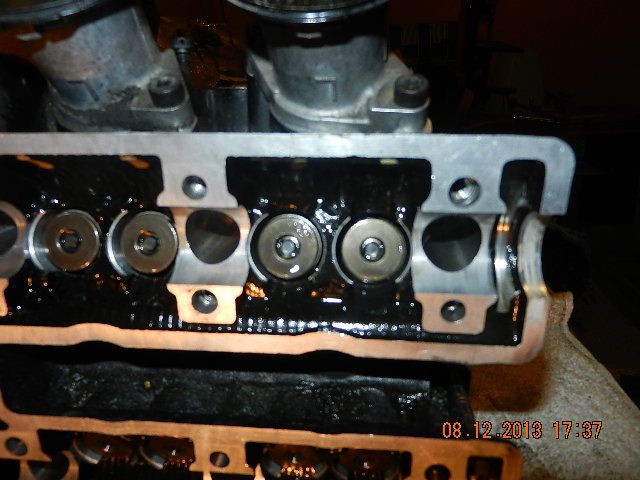
The important thing is that both of the keepers are seated, visibly centered on the valve stem and both the same depth below the surface (which means they are both properly locked into the groove on the top of the valve stem).
At this point, the only thing remaining to go back in the cylinder head are the shims and buckets, which is easy stuff for tomorrow, because with this tough part of the job done, it is Miller time!


